When selecting a TRIAC, engineers often encounter this scenario:
Why are there three distinct models—D, E, and F—when the voltage rating, current rating, and package type are identical?
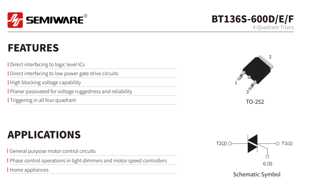
Take Semiware’s BT136S-600D, BT136S-600E, and BT136S-600F as examples: all three are 600V, 4A RMS, four-quadrant TRIACs housed in TO-252 (DPAK) packages, primarily used in applications such as motor control, AC dimming, phase control, and home appliance circuits.
The actual differences lie mainly in the gate trigger current, holding current, latching current, and dV/dt characteristics.
I. Differences in Key Parameters for BT136S-600D/E/F
The most obvious difference between the BT136S-600D, E, and F models is the gate trigger current; however, when making a selection, one must also consider the variations in holding current (IH), latching current (IL), and dV/dt parameters. Details are as follows:
| Part Number | IGT (Q1/Q2/Q3) | IGT (Q4) | IH | dV/dt |
| BT136S-600D | ≤5mA | ≤10mA | ≤15mA | ≥50V/μs |
| BT136S-600E | ≤10mA | ≤25mA | ≤25mA | ≥100V/μs |
| BT136S-600F | ≤25mA | ≤70mA | ≤30mA | ≥150V/μs |
IGT, IH, IL, and dV/dt each correspond to specific design considerations.
- IGT: How much gate trigger current is required?
A lower IGT generally means the device requires less gate current to meet triggering conditions. Particular attention should be paid to Quadrant 4 (Q4), as the BT136S-600D/E/F series supports four-quadrant triggering.
- IH: Holding Current
IH is a critical parameter representing the current required to maintain the TRIAC in the ON state after it has been triggered.
In applications involving low-current loads, phase control, or rapid current fluctuations, IH can determine whether the TRIAC maintains stable conduction.
- IL: Latching Current
IL represents the latching current; it describes the specific anode current level the device must reach immediately after triggering to reliably maintain conduction.
4. dV/dt: Design margin for rapid voltage changes
This parameter warrants particular attention for inductive loads, motors, switching power supplies, and AC switching circuits subject to rapid voltage changes.
II. BT136S-600D vs. BT136S-600E vs. BT136S-600F: Selection Guide
2.1 BT136S-600D
The BT136S-600D has the lowest maximum IGT (gate trigger current), making it ideal for control circuits with limited gate drive capability.
Examples:
- Controllers with limited output current where lower gate drive requirements are desired;
- Use of optocouplers with low output current or other low-power drive circuits;
- Stable operating environments where dV/dt requirements are not particularly stringent;
- Applications primarily involving resistive loads, such as heaters or incandescent lamps.
In actual PCB design, gate traces should be laid out optimally, and the need for snubber networks (such as RC snubbers) should be evaluated based on load characteristics.
2.2 BT136S-600E
The BT136S-600E falls between the D and F variants, offering a balanced specification regarding gate drive requirements and dV/dt capability.
It is a suitable candidate for many general-purpose AC switching, dimming, and small motor control applications.
Examples:
- MCUs or other controllers with sufficient gate drive current margin;
- Use of TRIAC-output optocouplers or other drive circuits;
- Applications such as fan speed control, small motors, LED dimming, coffee machines, and water pumps;
- Resistive or general inductive loads requiring a balance between drive capability and dV/dt performance.
2.3 BT136S-600F
The BT136S-600F has the highest gate trigger current requirement but also offers superior dV/dt capability; it should be the primary choice for applications demanding higher dV/dt performance.
Examples:
- Circuits featuring dedicated gate drive or amplification stages;
- Loads such as motors or inductive components that are sensitive to rapid voltage changes.
Download datasheet:
Conslusion
If you are evaluating the BT136S-600D, BT136S-600E, or BT136S-600F, please contact Semiware to obtain datasheets, samples, and technical application support.