Introduction
In the 5G era, cellular base stations serve as the nerve endings of communication networks; their stability directly determines the communication experience for hundreds of millions of users.
However, base stations are typically deployed in open outdoor environments, making them highly susceptible to surge threats caused by lightning strikes and power grid fluctuations. Such events can lead to base station restarts, communication outages, or even the breakdown of core chips (such as SoCs and RF modules).
Drawing upon Semiware's extensive experience—spanning over a decade—in circuit protection, this article explores how to design a comprehensive surge protection solution.
I. What Causes Surges in Cellular Base Stations?
The surge risks facing base stations primarily stem from two sources:
1. Lightning Strikes: This includes both direct lightning strikes and induced lightning. Lightning discharges can induce transient overvoltages—reaching thousands of volts—on power lines, antenna feeder lines, and long-distance signal lines.
2. Power Grid Switching Operations: The switching of large inductive loads within the power grid, or the occurrence of short-circuit faults, can generate high-frequency transient interference.
II. Primary Surge Risks in Cellular Base Stations
1. Power Ports (AC/DC Inputs) - High-energy surges originating from lightning strikes or power grid switching events.
Risk: Burnout of power modules; system restarts or failures.
Typical Scenario: Outdoor base stations connected via long-distance power lines.
2. RF Antenna Interfaces – Lightning-induced surges transmitted via antenna feeder cables.
Risk: Damage to RF front-end modules and transceivers.
Particularly critical for equipment mounted at the top of towers.
3. Communication Interfaces (RJ45 / Fiber Optics / Control Lines) – Surges coupled via long-distance cables or ground potential differences.
Risk: Damage to PHY chips; data loss; communication interruptions.
III. Protection Strategies Based on System Architecture
By referencing a typical block diagram of a cellular base station, we can identify the critical protection points: the power input, external communication interfaces, and sensitive RF modules.
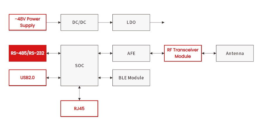
Detailed below are Semiware's specific protection solutions tailored to each of these critical nodes.
1️⃣ Power Input Protection: -48V Power Supply
Communication base stations typically utilize a -48V DC power supply. Since power lines are often lengthy and exposed to outdoor environments, they are highly susceptible to induced lightning surges.
Protection Strategy: Employ Gas Discharge Tubes (GDTs) with high energy-dissipation capabilities as the first stage of coarse protection to divert the majority of the lightning current.
Recommended Devices:
| Product Model | Type | Key Specifications | Function |
| SG6D09B800 | Gas Discharge Tube (GDT) | 800V, 20KA, 8.0×8.5×16.3mm | Primary Protection: Dissipates high-energy surges generated by lightning strikes; features high voltage withstand capability. |
| SG2R09B090 | Gas Discharge Tube (GDT) | 90V, 20KA, 8.3×8.3×6.0mm | Secondary Protection: Used in conjunction with varistors or TVS diodes to reduce residual voltage. |
2️⃣ Industrial Control Interface Protection: RS-485 / RS-232
These interfaces facilitate communication between the base station and the monitoring center or other peripheral equipment; given the length of these lines, they serve as primary conduits for surge intrusion.
Protection Strategy: Implement a combined protection scheme utilizing a "GDT + TVS + Thyristor" configuration. The GDT handles the discharge of high currents, the TVS ensures rapid response and voltage clamping, and the Thyristor (TSS) addresses high-frequency interference.
Recommended Devices:
| Product Model | Type | Key Specifications | Function |
| SG3D05B090 | GDT | 90V, 5KA, 5.0×5.0×7.5mm | Blocks high voltage and discharges current. |
| SVB60B15 | TVS Diode | 16.7–18.5V, 600W, SMB | Voltage Clamping: Rapid response; limits voltage within a safe range. |
| SE23T40B712B | TVS Diode Array | +7/-12V, 55pF, ±25KV, SOT-23 | Signal Line Protection: Low capacitance; prevents signal distortion and provides ESD protection. |
| STB100B6.0 | Thyristor (TSS) | 6.0V, 6KV, 100A, SMB | Overvoltage Switch: High reliability; designed for precision circuit protection. |
3️⃣ High-Speed Data Interface Protection: USB 2.0
USB interfaces are used to connect debugging tools or storage devices; the associated chips are typically highly fragile and demand strict signal integrity.
rotection Strategy: Utilize low-capacitance ESD diodes to prevent signal attenuation while simultaneously providing extremely high immunity against electrostatic contact discharge.
Recommended Devices:
| Product Model | Type | Key Specifications | Function |
| SE41T06U5.0LB | ESD Diode | 5V, ±20kV, 2pF, SOT-143 | High-Speed Signal Protection: Ultra-low capacitance; ensures lossless high-speed data transmission. |
4️⃣ Core RF Protection: RF Transceiver Module
The RF transceiver module serves as the "heart" of the base station; it is both expensive and highly sensitive.
Protection Strategy: Along the RF signal path, it is imperative to employ ultra-low capacitance ESD protection devices to avoid altering the antenna impedance matching and thereby compromising communication quality.
Recommended Components:
| Product Model | Type | Key Specifications | Function |
| SE06F10B5.0UA | Low Capacitance ESD Diode | 5V, 0.5pF, ±15KV, DFN0603-2L | RF Path Protection: Ultra-low capacitance; does not affect antenna impedance matching. |
5️⃣ Ethernet Interface Protection: RJ45
The RJ45 interface connects to the transmission network and is susceptible to induced lightning surges and ground potential rise (GPR) transients.
Protection Strategy: A Gas Discharge Tube (GDT) is typically employed at the transformer side for common-mode protection, while a low-capacitance TVS array is utilized at the data line side.
Recommended Components:
| Product Model | Type | Key Specifications | Function |
| SG3225B800 | GDT | 800V, 1KA, 0.5pF, 3.2×3.2×2.5mm | Common-mode protection; dissipates induced lightning surges. |
| SE3D35B3.3MA | ESD Diode | 3.3V, 0.6pF, ±30KV, SOD-323 | Low-voltage data line protection. |
| SESRV05-4A | TVS Array | 5V, 0.8pF, ±15KV, SOT-23-6L | Multi-channel protection. |
| STB100B58 | Thyristor | 58V, 6KV, 100A, SMB | High-voltage, high-current protection. |
| STB100B400 | Thyristor | 400V, 6KV, 100A, SMB | High-voltage, high-current protection. |
🔚 Conclusion
Developing a comprehensive surge protection solution for cellular base stations hinges on selecting appropriate protection components—tailored to the specific characteristics and risk levels of each interface—and establishing a multi-stage protection architecture. This approach serves to maximize the operational safety and stability of the cellular base station.
Click here to explore Semiware’s specialized solutions for this field:
🔗 https://en.semiware.com/applications/cellular-base-station/
You are also welcome to contact us at any time—we would be delighted to discuss how to formulate the optimal protection strategy for your specific design requirements.


Comments (0)