USB interfaces are one of the most common external interfaces in electronic devices. Computers, industrial equipment, network equipment, set-top boxes, and various consumer electronics products may connect to external devices via USB interfaces.
I. Why are USB interfaces susceptible to ESD?
USB interfaces are typical open I/O interfaces, and users frequently plug and unplug them during use. When a person, connector, or other device carrying static electricity comes into contact with the USB interface, ESD current may enter the device along the USB circuitry.
Common effects include:
- USB device not being recognized
- Data transmission interruption
- USB controller reset
- MCU abnormal restart
- System crash or unstable communication
- In severe cases, permanent damage to the interface IC
Therefore, adding a suitable ESD protection device near the USB interface is an important design measure to improve interface reliability.
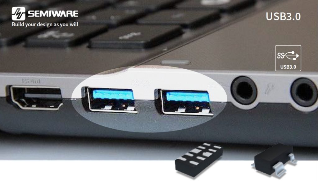
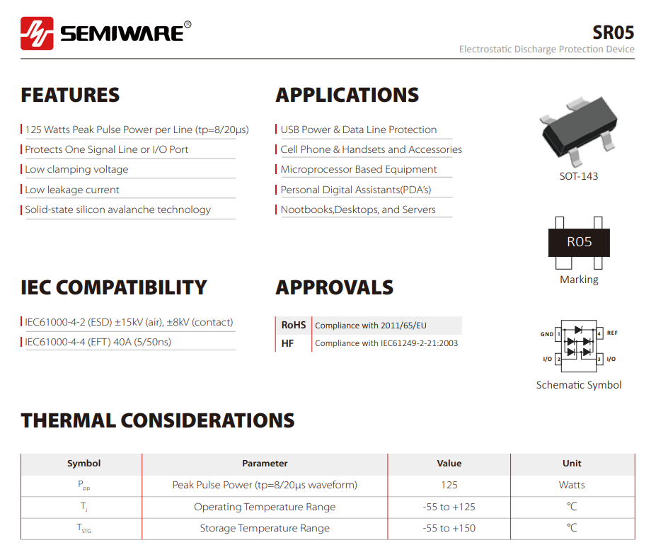
The Semiware SR05 TVS diode is an ESD protection device in an SOT-143 package, operating at 5V, and can be used for ESD protection of USB power and data cables.
II. SR05 TVS Diode Array Working Principle and Main Characteristics
2.1 SR05 Working Principle
- The SR05 employs solid-state silicon avalanche technology, maintaining low leakage current under normal operating conditions.
- When the USB interface experiences transient overvoltages such as ESD, the device quickly enters the conduction state, providing a discharge path for the transient current and limiting the voltage to a low level, thereby reducing the risk of impact on subsequent circuits.
2.2 SR05 Main Parameters and Characteristics
| Parameter | SR05 |
| Package | SOT-143 |
| Reverse Stand-off Voltage (VRWM) | 5V |
| Peak Pulse Power (PPP) | 125W |
| Peak Pulse Current (IPP) | 5A |
| Clamping Voltage (VC) | 25V @ 5A |
| Junction Capacitance (CJ) | 2pF |
| Leakage Current (IR) | 1μA |
| ESD Protection | ±8kV Contact / ±15kV Air |
- Low Capacitance Design: The maximum I/O-GND capacitance is only 2pF, reducing the impact on USB data transmission and signal integrity, making it suitable for interface applications with high signal quality requirements.
- Low Leakage Current and Low Clamping Voltage: The maximum leakage current is only 1μA, while the low clamping voltage helps reduce the circuit load under normal operating conditions and reduces the impact of ESD transients on subsequent ICs.
- Reliable ESD Protection Capability: Complies with IEC 61000-4-2 ESD protection requirements, supporting ±8kV contact discharge and ±15kV air discharge.

III. Why is Capacitor Consideration Necessary for USB ESD Protection?
For USB interfaces, ESD protection devices cannot be judged solely by their ESD rating.
- USB data cables also handle high-speed signal transmission; therefore, the parasitic capacitance of the ESD protection device itself can affect signal integrity.
- If the capacitance of the protection device is too high, it may increase the signal load and cause problems such as signal waveform distortion and degraded transmission performance.
- The SR05 has a typical I/O-I/O junction capacitance of 1pF and a maximum I/O-GND capacitance of 2pF, which offers certain advantages in interface designs that require a balance between ESD protection and signal integrity.
IV. SR05 Application Circuit Reference
 ESD protection for USB USB2.0 USB3.0" class="wp-image-18331"/>
V. SR05 PCB Layout Considerations
For ESD protection">USB ESD protection, selecting the right device is only the first step; placement is equally important.
① It is recommended to place the SR05 near the USB connector.
This allows ESD entering the PCB to be quickly diverted by the protection device, reducing the propagation of transient energy into the motherboard.
② The path between the connector, SR05, and GND should be as short as possible, avoiding unnecessary vias and long traces.
③ The GND connection requires low impedance.
ESD current has a high transient peak value, therefore the GND loop cannot be designed simply like a normal low-speed signal line.
Short and wide connections should be used as much as possible, and the grounding loop should be designed reasonably according to the PCB structure.
④ Avoid unnecessary stubs on high-speed data lines.
For USB high-speed signals, the connection between SR05 and the signal line should also be as simple as possible, avoiding excessively long branches to reduce the impact on signal integrity.
VI. SR05 TVS Diode Array Application
6.1 USB Interface Protection
Typical Applications:
- USB Interface
- USB Data Cable
- USB Power Cable
- PC USB Port
- USB Hub and Peripherals
6.2 Computer and Peripheral Interface Protection
Laptops, desktops, servers, and various computer peripherals typically contain multiple USB interfaces. These interfaces need to be frequently connected to external devices, making them an important path for ESD to enter the system.
6.3 Consumer Electronics
External interfaces in mobile phones, tablets, digital devices, and other consumer electronics are also susceptible to static electricity from the human body.
6.4 Microprocessors and Sensitive I/O Interfaces
In addition to USB, the SR05 can be used for other I/O lines that are easily exposed to the external environment.
Typical applications include:
- Microprocessor I/O
- External Connectors
- Control Panel Interfaces
- Communication Equipment Interfaces
Summary: SR05: Provides simpler ESD protection for USB interfaces
If you are designing a USB interface or looking for alternatives such as the SR05 or ESD protection">USB ESD protection diode, please contact Semiware. We can assist you in selecting the appropriate ESD protection device based on your operating voltage, interface type, ESD rating, and PCB space requirements.