The core challenges for 77GHz radar stem from the RF front-end (MMIC, LNA, mixer) chips, which feature fine-geometry manufacturing processes and very low voltage tolerance, while the RF signal path is extremely sensitive to parasitic capacitance. Concurrently, the vehicle's 12V/24V electrical system generates significant transient high-voltage spikes; when combined with electrostatic discharge (ESD) risks during assembly and maintenance, this creates a dual-risk scenario where RF performance is easily degraded by capacitance changes and chips are susceptible to dielectric breakdown from high voltage. All relevant aspects must comply with automotive standards ISO 10605, ISO 7637, and ISO 16750.
I. Electrostatic Discharge (ESD) Risks
1、Sources of Static Electricity (Full Automotive Use-Cases)
1.1 Human Body Electrostatic Discharge (HBM)
Occurs during bumper removal/installation, radar housing connection/disconnection, and wiring harness mating. In dry environments, human body static can reach ±8–30kV (ISO 10605 automotive standards require ±15kV for contact discharge and ±25kV for air discharge). The instantaneous peak current reaches tens of amperes with a pulse width of tens of nanoseconds, easily causing breakdown of the RF chip's gate oxide layer.
1.2 Charged Device Model (CDM)
Chips accumulate charge during SMT placement and module assembly, leading to internal discharge upon power-up. Bare RF chips typically have a CDM tolerance of only 2–4kV, making them highly susceptible to latent damage.
1.3 Vehicle-Level Triboelectric Charging
Friction involving tires, vehicle body plastics, wiring harnesses, or windshield wipers against the housing causes charge to couple into the radar unit via the casing and connectors. Humid or condensation-prone environments facilitate the transfer of static electricity into the circuitry. 1.4. Electrostatic coupling via wire harnesses
2、Hardware port ESD failure points (risks specific to 77GHz systems)
2.1. RF antenna ports (highest risk)
Radar antenna arrays and microstrip feed lines are directly exposed without housing shielding; electrostatic discharge (ESD) can reach the LNA (Low-Noise Amplifier) and RF MMIC (transceiver chip) directly:
RF chip breakdown: The gate oxide layer of 77GHz RF transistors is extremely thin, with a typical breakdown voltage of <15V. Residual ESD voltage exceeding 12V can cause permanent burnout, manifesting as RF transceiver failure, loss of echoes, and a drastic reduction in detection range (limiting detection to close proximity).
High junction capacitance (>5pF) in conventional TVS diodes causes a surge in 77GHz signal insertion loss, degradation of the standing wave ratio (SWR), and a collapse in the signal-to-noise ratio (SNR); standard ESD components cannot be placed directly on RF ports, and component selection is strictly constrained by high-frequency requirements.
Latent "soft" damage: Increased chip leakage current and degraded noise figure (NF) lead to increased radar false alarms/missed detections and unstable ranging readings; since there is no obvious physical burnout, troubleshooting is extremely difficult.
2.2. High-speed communication interfaces
LVDS, Automotive Ethernet, CAN/CAN-FD:
ESD causes breakdown of differential pair chip pins and damage to SERDES high-speed transceivers;
Transient interference triggers communication errors, packet loss, radar disconnection, and random failures of ACC (Adaptive Cruise Control) or AEB (Autonomous Emergency Braking) systems;
High-speed lines also limit the junction capacitance of protection devices; excessive capacitance directly results in insufficient bandwidth and signal distortion.
2.3. Power input interfaces
Electrostatic discharge travels along power lines into DC-DC converters and LDO (Low-Dropout) regulator chips, causing power shorts or damage to voltage regulation loops, resulting in the radar failing to power up or repeatedly rebooting.
2.4. Housing and shielding ground
Electrostatic discharge penetrates the internal ground plane via the metal housing, creating ground bounce noise; RF signals become noise-modulated, leading to errors in target identification. 3. Typical ESD Failure Classifications
Hard Failure: Chip short-circuit or open-circuit; radar completely loses RF functionality or fails to power up;
Soft Failure (High industry incidence): Chip parameter drift, increased noise, reduced sensitivity; faults recur under high or low-temperature conditions;
Latch-up: High ESD voltage triggers latch-up in the CMOS main controller, causing sustained high-current draw, chip overheating, system freeze, or even burnout.
II. Overvoltage / Transient Surge Risks
These originate entirely from the vehicle's 12V/24V power network and are defined by ISO 7637-2 and ISO 16750. They fall into four categories: load dump, switching transients, load switching, and battery disturbances. Risks are concentrated in the power circuit, with high-voltage coupling causing crosstalk into the RF section.
Sudden disconnection of heavy vehicle loads (e.g., blower motors, compressors) generates extremely high voltage spikes on the battery line:
12V vehicles: ISO Pulse 5a with a peak of 174V and pulse width of several hundred milliseconds; 24V systems can reach over 350V;
Hazards: Overvoltage causes direct breakdown of radar power chips and MMIC power supplies; high voltage breaks down the dielectric of power MLCC capacitors, leading to leakage or short circuits; instantaneous power drops cause massive radar resets—resulting in ACC target loss during high-speed driving and posing significant functional safety risks;
Derived risks: High voltage couples into the RF layer via power traces, breaking down RF passive components and microstrip line dielectrics.
2、Various Automotive Switching Transients (ISO 7637 Pulses 3a/3b)
Motor start/stop, relay actuation, and headlight switching generate high-frequency positive and negative spikes: ±100V to ±200V, with durations ranging from nanoseconds to microseconds;
High voltage causes breakdown in LDOs and DC-DC converters;
Spikes couple into the RF signal path, causing instantaneous signal saturation and temporary radar blindness;
Repeated, long-term stress accelerates the aging of power capacitors and resistors, leading to a year-over-year decline in reliability.
3. Cold-cranking voltage drop + Reverse voltage
During cold-start cranking, the battery voltage drops to 6–9V, causing the power management IC (PMIC) to trigger undervoltage lockout (UVLO) and the radar to operate intermittently;
Accidental reverse battery connection results in -12V/-24V reverse voltage; without reverse-polarity protection, power stages across the system would suffer batch failures.
4、AC ripple and superimposed stress
Generator rectification ripple and high-frequency ripple from inverters (in new energy vehicles) superimpose with surges; long-term voltage stress accelerates fatigue in PCB traces and BGA solder joints; switching noise from OBCs and motor controllers in new energy vehicles easily couples into the radar power supply, creating continuous voltage disturbances.
III. Unique constraints distinguishing 77GHz mmWave radar from low-frequency radar (Protection Dilemma)
1、Parasitic capacitance limits
With the extremely short wavelength of 77GHz signals, the junction capacitance of any protection component on the RF path must be kept at ≤0.3–0.5pF; conventional TVS diodes and varistors have junction capacitances in the tens of pF—installing them causes RF losses exceeding 1dB, rendering the radar's sensitivity useless. ESD protection">ESD protection requires RF-specific ultra-low-capacitance TVS diodes, SCRs, or series inductors to resonate out the parasitic capacitance.
2、Extremely low voltage tolerance of RF chips
While 24GHz radar RF components typically withstand voltages above 20V, the gate breakdown voltage of advanced-process 77GHz MMICs is only 10–15V; if surge residual voltage exceeds 15V, permanent damage is highly likely, necessitating extremely high precision in TVS clamping (clamping fluctuation within ±5%).
3、Coupling exacerbated by dense PCB routing
77GHz microstrip lines are fine-pitched, and the spacing between power and RF layers is minimal; power surges and ESD easily crosstalk into the RF path via interlayer capacitance, with voltage noise directly modulating the radar echo and generating numerous ghost targets.
4、Risks of superimposed stresses
Simultaneous occurrence of ESD, Electrical Fast Transients (EFT), and surges can easily cause single protection components to fail due to thermal overload; thermal cycling and vibration can cause solder joint cracking in protection components, degrading protection capabilities.
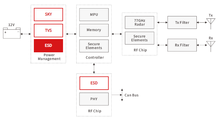
III. Circuit Protection Application Block Diagram
Learn More
For more details on circuit protection solutions against ESD and overvoltage for 77GHz millimeter-wave radar, please visit: https://en.semiware.com/applications/77ghz-radar/
About Semiware
Semiware is a comprehensive provider of circuit protection solutions, serving customers in the electronics, automotive, and industrial markets by leveraging its expertise in semiconductor technology and end-product applications. We offer an extensive portfolio of circuit protection devices—including overvoltage protection, overcurrent protection, composite protection, discrete components, and advanced packaging technologies—to meet diverse customer needs. Through our global network of EMC laboratories and Field Application Engineers (FAEs), we deliver complete solutions and product portfolios. For more information, please visit https://en.semiware.com.