The T-BOX is the core of the vehicle's remote communication system. Load dump is a fatal threat from long-term high-energy, high-voltage power supply, while ESD">ESD is a nanosecond-level instantaneous high-voltage surge across all ports. The failure modes, affected ports, and protection schemes of these two are completely different, making them two essential tests for T-BOX mass production EMC and reliability testing.
I. Load Dump Risk
1、Generation Mechanism
When the vehicle's alternator is charging at high power, battery connections may become loose, corroded, or intentionally disconnected. The battery acts as a natural voltage stabilizer and buffer for the vehicle; when disconnected, the magnetic field energy stored in the alternator's excitation winding has no discharge path, resulting in a continuous high-voltage pulse on the power bus.
Typical operating conditions: high-current charging during startup/climbing, battery disconnection during maintenance, and loose connections due to bumpy rides.
2、Core Electrical Characteristics (12V Passenger Vehicle System)
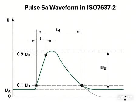
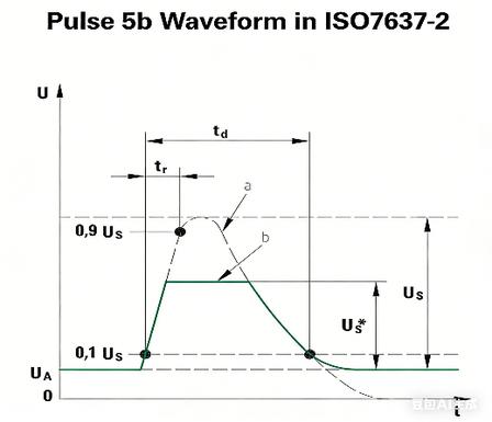
Based on ISO 16750-2 (current mandatory standard) and ISO 7637-2 (old standard), pulse 5a/5b:
- Peak Voltage: 5a (unsuppressed generator): 79~101V; 5b (with vehicle suppression): 65~87V
- Duration: 40~400ms (millisecond level, much longer than ESD">ESD nanosecond level)
- Equivalent internal resistance: 0.5~4Ω; single pulse energy can reach tens to hundreds of joules
- ISO 16750-2 stringent requirement: 10 consecutive pulses, 1 minute interval, assessing the risk of device burnout due to cumulative heat generation.
3、Affected Ports of the T-BOX
Only constant 12V power input (ACC/BAT) will affect all circuits drawing power from the main power supply:
- Pre-amplifier DC-DC step-down chip (most easily burned out)
- Power MOSFETs, input filter electrolytic capacitors
- Main control MCU, 4G/5G RF baseband, CAN transceiver power rails
- Rear USB, Ethernet, LIN bus secondary power supplies
4、Typical Load Drop Failure Phenomena
- Permanent damage from thermal breakdown: Ordinary low-power TVS diodes may experience instantaneous overpower explosion, open circuit/short circuit; internal power transistors in the DC-DC converter may melt, preventing the entire unit from powering on.
- Electrolytic capacitors may leak, bulge, or explode due to overvoltage; PCB copper foil may melt due to overcurrent.
- Irreversible breakdown of the internal PN junction of the chip: Short circuit in the power supply pins of the MCU and RF chip, resulting in permanent failure of remote wake-up and 4G communication.
- Hidden damage: Device parameter drift, frequent crashes at low temperatures, packet loss in remote control, and abnormal satellite acquisition by the positioning module.
II. Electrostatic Discharge (ESD">ESD) Risk: Instantaneous high-voltage surge across all ports
1、Generation Mechanism
Following ISO 10605 (Automotive-Specific ESD">ESD Standard), three discharge models are defined:
- Human Body Model (150pF/330Ω): Passengers getting in and out of the vehicle, touching the T-BOX metal casing, or the USB interface;
- Metal Tool Model (330pF/330Ω): Maintenance personnel plugging and unplugging connectors, or touching the test probe;
- Insulated Human Body Model (330pF/2kΩ): Static electricity accumulation in the dry interior of the vehicle during winter.
ESD">ESD Characteristics: Rise time < 1ns, peak voltage ±8kV contact / ±25kV air discharge, duration only a few hundred nanoseconds, instantaneous current tens of amperes, low energy but extremely high voltage.
2、All High-Risk Ports in the T-BOX
- External Physical Interfaces (Highest Risk): USB/Type-C, Automotive Ethernet (ETH), CAN/CAN FD, LIN Bus, RS232 Debug Port, SIM Card Slot, TF Card Slot, External Antenna Metal Connector, Button/Indicator Metal Housing
- Metal Housing, Connector Metal Shielding: Static electricity can couple directly into the internal ground plane through the housing, generating ground bounce noise.
- Power, Reset, GPIO, RF Control Signal Lines: Static electricity can infiltrate through capacitive/inductive coupling in the wiring harness.
3、ESD Hidden Coupling Risk
Even without direct contact with the pins, strong ESD electromagnetic fields can induce high voltages through spatial coupling on the inner layers of the PCB, damaging high-precision RF and high-speed differential signals (ETH/CAN FD), compromising signal integrity, and causing random communication failures that are extremely difficult to reproduce.
III. Key Design Considerations for T-BOX Protection
(I) Multi-Stage Load Throw Protection (BAT Input)
- Level 1 Discharge (Main TVS, Automotive-Grade High Power): Utilizes AEC-Q101 high-power SM8S or 5KP series TVS, clamping voltage 33~36V, withstands 10 load throw pulses, placed close to the input terminals, with short, thick traces and extensive grounding for heat dissipation.
- Level 2 Current Limiting and Filtering: Series power PTC/power resistor + large-capacity low ESL electrolytic capacitor + MLC X7R high-voltage ceramic capacitor to suppress residual surges and protect the downstream DC-DC converter.
- DC-DC Converter Selection Constraints: Input withstand voltage ≥40V, built-in overvoltage/overcurrent/thermal shutdown to prevent high-voltage backflow damage to downstream circuitry.
- Layout Criteria: TVS ground is directly connected to input ground, avoiding MCU and RF sensitive areas to prevent high-voltage coupling and crosstalk signals.
(II) ESD Full-Port Hierarchical Protection
- High-speed differential bus (CAN FD / Automotive ETH): Ultra-low junction capacitance automotive-grade ESD array (Cj<1.5pF), such as the PESD series, providing one-to-one protection between differential pairs without damaging differential impedance, rated at ±25kV air discharge.
- Low-speed single-ended signals (LIN, GPIO, debug port): General-purpose automotive-grade ESD diode array, with parallel 0Ω/100Ω current-limiting resistors to suppress latch-up current.
- USB/SIM/TF card slot: Dual-channel ESD for power and data, with a single-point reliable grounding on the metal casing. The casing is isolated from the internal ground by a series ferrite bead, blocking ground bounce conduction.
- Overall structural grounding: Multiple grounding points on the casing and 360° grounding on the connector shielding shell shorten the ESD discharge loop and reduce spatial coupling interference.
IV. Application Block Diagram Provided by Semiware
 ESD.jpg" alt="Load Dump and ESD Risks Facing Vehicle T-BOX" title="Load Dump and ESD Risks Facing Vehicle T-BOX" alt="" class="wp-image-17925"/>
Learn More
As a professional provider of circuit protection solutions, Semiware offers complete T-Box circuit protection solutions. For more information, please visit: https://en.semiware.com/applications/t-box/