I. Overview of Power Conversion System (PCS)
A power conversion system (PCS) is the core power conversion unit in an energy storage system. It is responsible for enabling bidirectional energy flow between the battery system and the power grid, including AC/DC and DC/AC conversion during charging and discharging.
A typical energy storage system usually consists of the following components:
- Battery Pack
- Battery Management System (BMS)
- Energy Management System (EMS)
- Power Conversion System (PCS)
- Auxiliary Power Supply and Communication Control Unit
The PCS not only performs energy conversion but also needs to ensure long-term stable operation in complex electromagnetic environments; therefore, its protection design is crucial.
II. Analysis of Static Electricity and Surge Sensitive Nodes in Energy Storage Converters
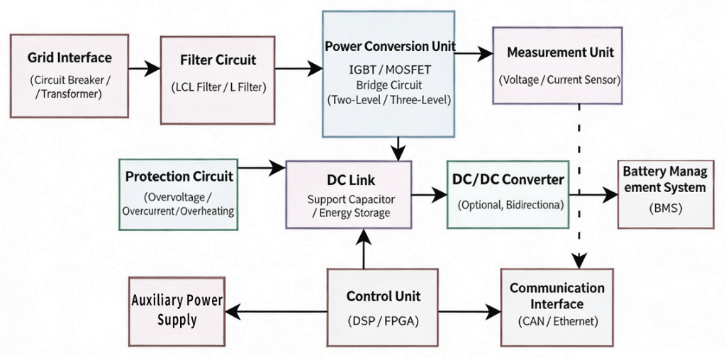
Based on the modular PCS architecture, typical sensitive nodes can be summarized as follows:
- Grid Interface (AC Side)
- Sensitive Locations: Circuit breaker, transformer terminals
- Operating Voltage: 380V AC (Industrial three-phase system)
- Typical Standard Environment: IEC 61000-4-5 (Surge: Line-to-ground ±4kV / Line-to-line ±2kV)
👉 Characteristics: This is the strongest energy surge point in the system, requiring a multi-stage discharge structure design.
- Filter Circuit (EMI Filter)
- Sensitive Locations: Inductor and capacitor connection nodes
- Operating Voltage: AC bus voltage (PCC point)
- Typical Standard Environment: IEC 61000-4-4 (EFT: ±4kV Fast Transient)
👉 Characteristics: Extremely sensitive to high-frequency transients, easily causing control malfunctions.
- Power Stage
- Sensitive Locations: IGBT driver, current sampling, DC bus
- Operating Voltage: Approximately 800V DC bus system
- Typical Standard Environment: IEC 61000-4-2 (ESD: System-level contact ±6kV / Air ±8~15kV)
👉 Characteristics: ESD primarily affects the drive and control sides, not the main power devices themselves.
- DC Link
- Sensitive Locations: Both ends of the bus capacitor
- Voltage Rating: Commonly found in 600V–1500V DC systems
- Relevant Standards: IEC 62109 / UL 1741 (Insulation and withstand voltage requirements)
👉 Characteristics: Withstands the combined impact of energy surges and switching transients.
- DC/DC Conversion Module
- Sensitive Locations: Input/Output Terminals, Switching Nodes
- Typical Standard Environment:IEC 61000-4-5 (Bidirectional Surge)
👉 Features: High-voltage and low-voltage side isolation design is particularly critical.
- Battery Management System (BMS)
Sensitive Locations: CAN Communication, Voltage Sampling Terminals
- Battery Voltage: Approximately 3.0–4.2V per cell
- Typical Standard Environment: IEC 61000-4-2 (ESD System Level: ±8kV Contact / ±15kV Air)
👉 Features: Communication ports are the most common ESD intrusion path.
- Control and Auxiliary Power Supply
- Sensitive Locations: 3.3V / 5V Logic Power Supply
- Typical Standard Environment: IEC 61000-4-4 (EFT: ±2kV)
👉 Features: Low-voltage systems are more sensitive to transients and prone to logic malfunctions.
- Communication Interface (CAN / Ethernet)
- CAN Bus Voltage: ±5V differential signal
- RJ45 Interface: Gigabit Ethernet
- Typical Standard Environment: IEC 61000-4-2 (ESD); IEC 61000-4-5 (System-level Surge Enhancement Design)
👉 Features: Long cable systems are highly susceptible to coupling with external surges and ESD interference.
III. Surge and ESD Protection Scheme Design for Energy Storage Converters and Semiware Device Selection Reference
Energy storage PCS typically adopts a design approach of "tiered protection + multi-device collaboration."
- DC Side Protection (High Voltage DC System)
🔹 Primary Protection (Energy Discharge):
Gas Discharge Tube (GDT) between GND and PE provides a high-current surge discharge path.
Function: Absorbs lightning strikes/high-energy surges from the grid.
🔹 Secondary Protection (Fine Clamping):
High-power TVS (such as SM8S58CA series) is recommended, provides fast-response voltage clamping.
Function: Suppresses residual surge energy, protecting DC/DC converters and control circuits.
🔹 Post-Stage Protection (Low-Loss Design):
- MOSFET reverse connection protection (low RDS(on) scheme)
- Schottky diode for negative voltage suppression
- Low leakage TVS at the battery terminal (<1μA level)
Design Focus: Achieving a balance between efficiency and protection.
- AC Mains Interface Protection
Typical Applications:
- MOV (Metal Oxide Varistor), such as 14D/20D/25D 471K series
- GDT (Gas Discharge Tube), such as SG2R08B600
Design Goal: Meet IEC 61000-4-5 system-level surge test (4kV–8kV level)
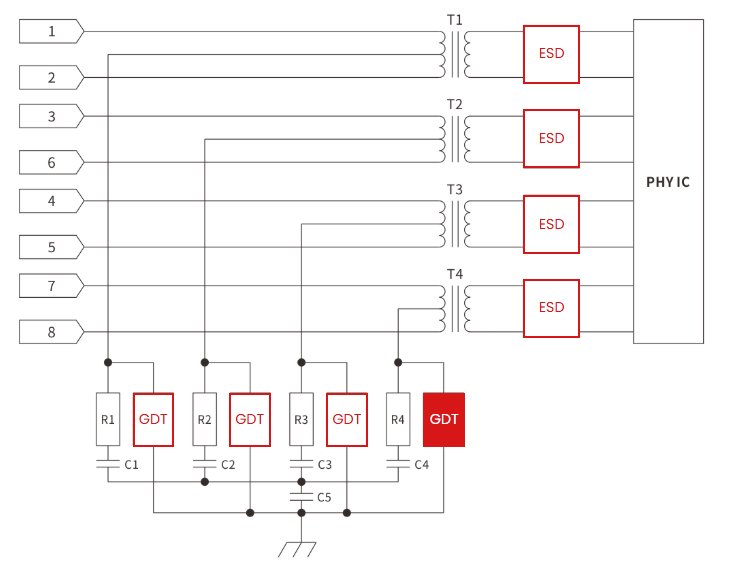
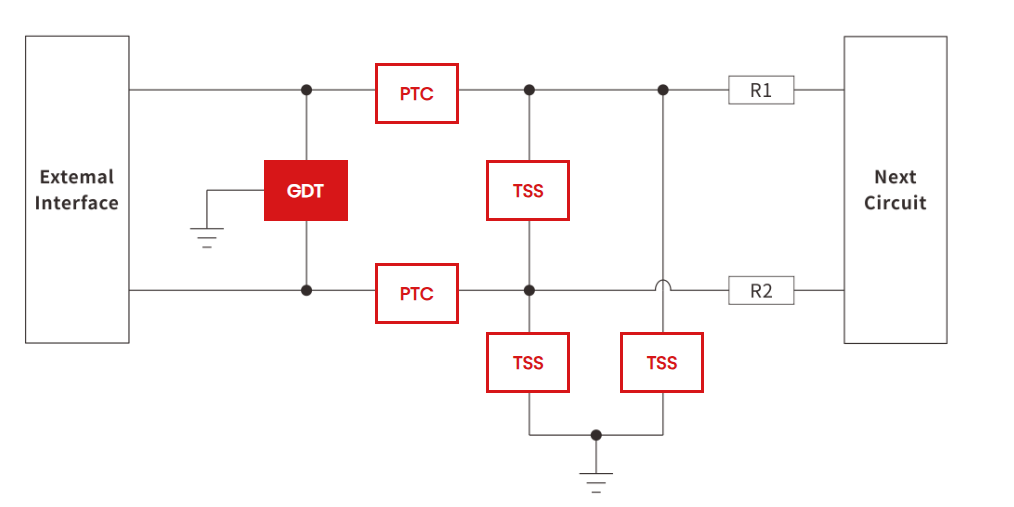
- Communication Interface Protection Solutions
🔹 Gigabit Ethernet (RJ45):
Typical Structure:
- Pre-stage GDT (such as SG3D05B090, for high current dissipation)
- Post-stage Low Capacitance ESD Diode (such as GBLC03CI, as low as 0.6pF)
Design Goal: Improve system-level ESD immunity and reduce high-speed signal insertion loss
🔹 RS485 Bus:
Recommended Solution:
Use a low residual voltage Protection Thyristor (TSS), such as P0080SC
Design Goal: Improve surge withstand capability (withstand 6kV surge under 10/700μs waveform)
Summary
The protection design of the energy storage converter PCS is essentially a systems engineering project of:
"Energy graded discharge + fine signal protection + multi-standard collaborative design".
A reasonable ESD and surge design can not only improve system reliability but also significantly reduce the field failure rate, especially in long cable, high-voltage DC, and complex power grid environments.


Comments (0)