Introduction
The two-wire fire alarm bus is a mature and widely adopted PowerBus technology; by utilizing a single pair of twisted-pair wires to simultaneously transmit DC operating power (24V/28V) and bidirectional communication signals, it serves as the core networking backbone for modern fire alarm systems. This bus architecture enables seamless interconnection among fire alarm control panels (FACPs), various types of detectors, and intelligent fire linkage modules.
Compared to traditional multi-wire fire alarm systems, the two-wire bus solution significantly simplifies on-site wiring and reduces engineering costs. However, extensive building-wide cabling exposes the bus to complex electromagnetic interference and risks of electrical faults—issues that can lead to communication interruptions, device disconnection, false alarms, or even total system failure.
This article systematically outlines the core characteristics of the two-wire fire alarm bus, analyzes typical electrical threats encountered during actual operation, and proposes a comprehensive three-stage EMC (Electromagnetic Compatibility) and overcurrent protection architecture based on a "GDT+PPTC+TVS" configuration. This optimized solution strikes a balance between surge suppression, electrostatic protection, overcurrent limiting, and signal integrity, thereby significantly enhancing the long-term operational reliability of on-site fire alarm equipment.
I. Core Characteristics of Fire Alarm Two-Wire Bus
Compared to traditional multi-wire systems, the two-wire bus requires only a single pair of wires for both power supply and data communication, significantly reducing wiring costs and installation complexity. Its main features include:
- Power supply and communication via two wires, reducing wiring costs;
- Long transmission distance, with a theoretical communication range of up to 1,500 meters;
- Flexible networking, supporting topologies such as bus and star configurations;
- Support for protocols like Modbus RTU, facilitating system integration.
II. Typical Electrical Threats and Field Risks
Since bus lines typically span an entire building—or even connect multiple floors—they are susceptible to electrical threats such as lightning-induced surges, electrostatic discharge (ESD), and short circuits.
Damage to the bus interface can range from communication anomalies to detectors going offline, false alarms, or even a complete system failure.
Common risks include:
| Threat | Typical Source |
| Surge | Lightning induction, power switching events |
| ESD | Human contact during installation or maintenance |
| Overcurrent | Short circuits, wiring errors, equipment failures |
III. Three-Stage Protection Architecture (GDT + PPTC + TVS)
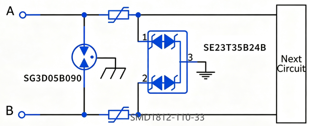
To enhance long-term system stability, a three-stage protection architecture utilizing GDT, PPTC, and TVS components is recommended.
Level 1 Protection: GDT for Surge Energy Dissipation
When the line is subjected to lightning-induced surges: The GDT activates first, shunting the majority of the surge current to the ground and reducing the impact energy experienced by downstream components.
👉 Suitable for protecting long-distance fire alarm bus lines in buildings.
Level 2 Protection: PPTC for Fault Current Limiting
In the event of a bus short circuit, module failure, or wiring error:
The PPTC rapidly increases its resistance to limit current, preventing sustained overcurrent from causing line overheating or component burnout. It automatically resets once the fault is cleared.
Level 3 Protection: TVS Absorption of Residual Surges and ESD
TVS diodes feature nanosecond-level response speeds, enabling precise clamping of residual surges and ESD to protect MCUs, bus transceivers, and communication interface chips.
At the same time, this ensures the signal integrity of PowerBus communications.
IV. Semiware Recommended Protection Devices
| Part Number | Device Type | Key Parameters | Channel | Package |
| SE23T35B24B | TVS Diode | 24V, 50pF, IPP=7A, ±30kV Air / Contact Discharge | 2-channel,Bidirectional, | SOT-23 |
| SD24C | TVS Diode | 24V, 24pF, IPP=7A, ±30kV Air / Contact Discharge | 1-channel, Bidirectional | SOD-323 |
| SG3D05B090 | Gas Discharge Tube | 90V ±20%, 1.5pF, 5kA Surge Capability | 2-channel,Bidirectional | Ø 5*7.5mm |
| SMD1812-110-33 | PPTC Resettable Fuse | 33V, Hold Current 1.1A, Initial Resistance 0.25Ω | / | SMD1812 |
V. Industry Standard Test Levels
This three-level protection solution has passed authoritative industry EMC certification tests, fully meeting the electromagnetic compatibility and reliability requirements of civil building fire alarm equipment:
- ESD Protection Test: Compliant with IEC 61000-4-2 standard, supporting ±30kV contact discharge and ±30kV air discharge;
- Vehicle & Industrial EMC Test: Compliant with ISO 10605 Level 4 standard, adapting to complex industrial and building electrical environments;
- Surge Immunity: Effectively improves the system's anti-surge interference capability, resisting lightning induction and power switching surges.
VI. Typical Application Scenarios
This cascaded protection solution is highly matched with all terminal and core equipment of intelligent fire alarm two-wire bus systems, covering full-scene fire protection equipment:
- Fire Alarm Control Panels (FACP)
- Smoke & Heat Detectors
- Bus Input/Output Linkage Modules
- Manual Fire Alarm Call Points
- Fire Linkage Control Equipment
- Fire Evacuation Voice Broadcast Systems
Conclusion
The three-stage protection architecture (GDT+PPTC+TVS) effectively mitigates the critical electrical risks facing two-wire fire alarm buses, including lightning surges, ESD interference, and line overcurrent or short-circuit faults. By employing staged energy dissipation, intelligent current limiting, and high-precision voltage clamping, the solution achieves an optimal balance between robust protection performance and the preservation of signal integrity.
Contact Us
If you need customized EMC protection schemes, detailed device datasheets, or technical support for fire alarm two-wire bus circuit design and debugging, feel free to contact the Semiware technical team.