GDTs are frequently used as front-end protection devices in surge protection designs for RS485, Ethernet, telephone lines, coaxial cables, and industrial communication lines.
They feature high insulation resistance, low parasitic capacitance, and strong surge current carrying capacity, making them particularly suitable for lines requiring both signal integrity and surge withstand capability.
However, a common question arises in engineering design:
Since GDTs can withstand large surge currents, why can't they be used directly to protect 220VAC power supplies? What are the differences between them and MOVs (Metal Oxide Discharge Valves)? Understanding this question is key to understanding the core of GDT selection.
I. What is a Ceramic Gas Discharge Tube?
A gas discharge tube (GDT) is a sealed ceramic device filled with inert gas and containing two or three metal electrodes. Under normal operating conditions, it exhibits an electrically "invisible" state (insulation resistance ≥ 1 GΩ). When a surge exceeding its breakdown voltage occurs, it can switch to a near-short-circuit state within nanoseconds—draining the surge current to ground—and then extinguish itself.
Key Features of the GDT:
- Due to its small capacitance and high current-carrying capacity, the GDT is the standard first-level protection element for signal line surge protectors (SPDs) in RS485, Ethernet, and telecommunications circuits.
- Its internal electrode surfaces are typically coated with a special emissive agent to reduce electron emission energy and stabilize the arc. The ceramic material, due to its excellent thermal expansion coefficient matching and extremely high heat resistance, allows it to maintain structural stability in extreme environments.
Two Standard GDT Configurations:
- Dual-Electrode GDT: One gap, one protection mode (line-to-ground or line-to-line). This is the standard configuration for single-mode signal line protection.
- Triple-Electrode GDT: Two gaps share a common center electrode. Simultaneously protects both conductors of a balanced differential pair—crucial for RS485, twisted-pair, and telecommunications circuits.
II. How Does a GDT Work?
From an operational perspective, a GDT typically goes through the following stages.
① Normal Operating State
The line voltage is within the normal range. The GDT maintains a high-resistance state with very high insulation resistance, barely affecting normal signal or power supply operation.
② Surge Voltage Rise
When a lightning strike or other transient surge causes the voltage across the GDT to reach its discharge condition, the internal gas begins to ionize.
③ Breakdown and Arc Conduction
After gas ionization, a low-impedance discharge path is formed, and a large surge current is discharged through the GDT. At this time, the voltage across the GDT drops significantly, thus limiting the surge energy from entering subsequent circuits.
④ Surge End and Recovery
When the surge current decreases to a certain level, the arc cannot be sustained, the GDT stops discharging, and returns to a high-resistance state.
Therefore, the GDT is not always in operation; it only enters the conducting state when needed.
III. What Is the Difference Between GDT and MOV?
Both GDT and MOV can be used for surge protection, but their working mechanisms are different, so they are suitable for different application locations.
| Parameter | GDT | MOV |
| Protection Mechanism | Switching type | Clamping-type |
| Normal State | Very high impedance, ultra-low leakage | High impedance, but higher leakage than GDT |
| Capacitance | Very low, typically <2 pF | Generally higher |
| Surge Current | High surge current capability | High surge current capability |
| Typical Applications | Communication and signal lines, such as RS485, Ethernet, telecom, and RF | AC/DC power lines and power surge protection |
| Key Advantage | Low capacitance and strong surge current handling | Effective voltage clamping |
Therefore, GDT cannot simply replace MOV. In many surge protection solutions, GDT is generally used as a front-end high-energy discharge device in conjunction with MOV.
IV. Key Points for GDT Selection
① DC Breakdown Voltage: Represents the DC voltage range at which the GDT breaks down under specified test conditions.
When selecting, first ensure that the GDT's breakdown voltage is higher than the normal operating voltage of the line and the normal voltage fluctuations that may occur. (For example, Vdc for RS485 is usually selected as 90V or 120V.)
② Impulse Spark-over Voltage: Determines the response speed when a lightning strike occurs; it must be lower than the withstand voltage of the equipment.
③ Surge Current: Selected according to the installation environment. Common specifications are tested with standard surge waveforms such as 8/20μs (5kA, 10kA, 20kA).
④ Parasitic Capacitance: GDTs typically have very low parasitic capacitance (<2pF), which is a very critical parameter for communication and high-speed signal lines.
⑤ Number of Electrodes:
- 2 Electrodes: Single-wire protection;
- 3 Electrodes: Used for differential signals (such as RS485), ensuring that both lines operate simultaneously for more balanced protection.
V. Common Application Scenarios of GDT
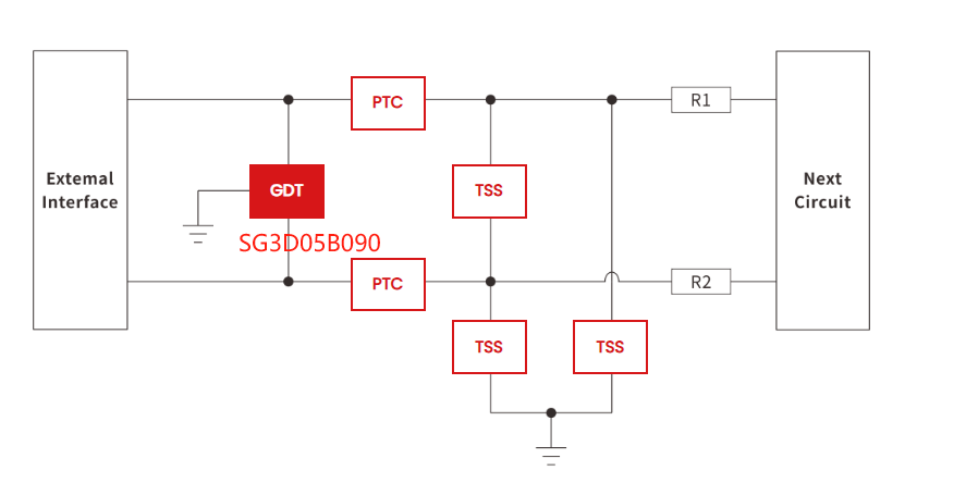
① RS485 / RS422 Communication Protection
GDTs can be used as front-end surge discharge devices, forming multi-level protection with PTCs and TSS thyristors.
② Ethernet Network Interface Protection
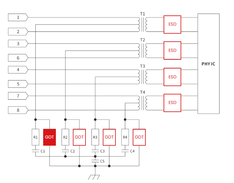
For outdoor APs, industrial switches, network cameras, and other long-distance network cable connections, network cables may introduce external surges into the equipment.
③ RF / Wi-Fi Antenna Protection
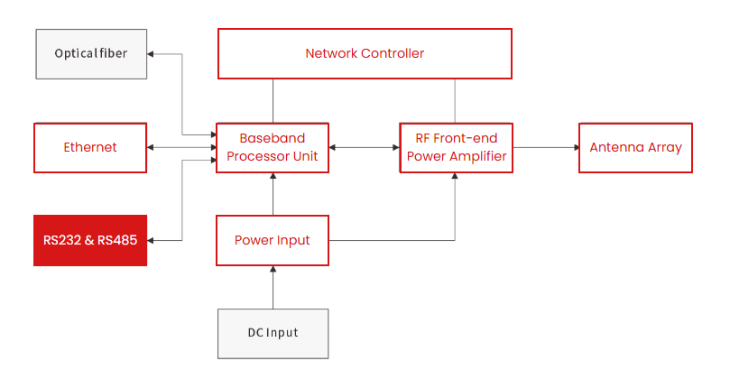
Outdoor antennas, Wi-Fi APs, and antenna ports of wireless communication equipment may be affected by lightning-induced surges.
Summary
When selecting a GDT, the line operating voltage, surge level, breakdown voltage, current carrying capacity, parasitic capacitance, and protection topology should be comprehensively considered to select a GDT that matches the system requirements.
For communication, high-speed signal and power surge protection, different applications have different requirements for GDT. Only by properly matching device parameters can a better balance be achieved between surge protection capability, signal integrity and system reliability.
👉 If you are selecting a GDT for RS485, Ethernet, Telecom, RF, DC/AC power input, or other external interfaces, please contact Semiware. Our engineers can provide GDT selection support based on your specific application.