Introduction
Power Line Carrier (PLC) communication technology transmits high-frequency carrier signals alongside standard power-frequency electrical energy over existing AC mains cabling. It is widely used in smart meters, the energy IoT, smart home systems, and industrial IoT devices.
Unlike standard low-voltage communication interfaces, PLC signals travel directly over power lines. The PLC coupling circuit maintains a direct electrical connection to the L/N mains lines; consequently, transient disturbances from the power grid can enter the PLC front-end via the coupling network, subjecting the carrier chip and its analog front-end to electrical stress.
This explains why communication may function perfectly during the prototype debugging phase, yet fail—manifesting as module lock-ups, random disconnections, or chip burnout—during EMC certification or field deployment. The root cause is often the lack of adequate ESD (Electrostatic Discharge) and surge protection at the PLC port.
I. What Sources of ESD and Surge Interference Do PLC Ports Face?
Because the PLC communication coupling circuit connects directly to the low-voltage power grid, it is exposed to two types of interference: surges and electrostatic discharge (ESD).
1) Surges (High-Energy Transient Overvoltage)
- Lightning-induced surges: Direct lightning strikes on the equipment are not required; electromagnetic induction on overhead cables can generate pulses ranging from several thousand to over ten thousand volts. Outdoor-deployed devices, such as smart meters and data concentrators, are at the highest risk.
- Grid switching surges: High-voltage spikes generated by grid switching operations, transformer energization/de-energization, capacitor bank switching, and the startup or shutdown of high-power loads.
- Load-induced disturbances: Pulse noise injected back into the power line by on-site variable frequency drives (VFDs), EV charging stations, and high-power appliances during startup or shutdown.
- Surge characteristics: High energy; standard tests often utilize waveforms such as the 8/20 μs pulse. Once a surge penetrates the carrier coupling circuit, it imposes significant electrical stress on the carrier chip, coupling transformer, and other front-end components, potentially causing irreversible hardware damage.
2) ESD (Electrostatic Discharge)
Static electricity from personnel—potentially reaching several kilovolts or higher—can discharge into the circuit board or terminals during manufacturing, assembly, field installation, or commissioning. Static electricity is generated by friction involving the device housing and by airflow carrying dust.
Impact of static electricity:
- Direct breakdown of carrier chip I/O pins or analog front-end components, leading to device failure;
- Micro-damage within the chip—while functionality appears intact during testing, issues such as carrier packet loss and communication interruptions occur during actual operation.
In addition to ESD and surge, actual PLC products may also be affected by factors such as Electrical Fast Transients (EFT), power-frequency overvoltage, and grid noise.
II. Why Is Designing Protection for PLC More Challenging Than for RS-485 or CAN Buses?
- Communication signals run directly on power lines: PLC signals are transmitted via power lines, and the coupling circuit must handle both the mains power-frequency voltage and the high-frequency carrier signal simultaneously; therefore, transient protection and signal integrity must be considered concurrently.
- Strict signal integrity constraints: Narrowband PLC operates in the kHz to hundreds-of-kHz range, while broadband PLC can reach tens of MHz. The parasitic capacitance and leakage inductance of protection components directly affect the carrier signal.
- Simultaneous exposure to high power-frequency voltage and low-level high-frequency signals: Protection components must withstand the rated mains voltage without significantly degrading the carrier signal, making component selection a complex balancing act.
- Compliance with specific product EMC requirements is necessary: the actual product must be evaluated against IEC 61000-4-2 (ESD), IEC 61000-4-5 (Surge), and applicable PLC-related standards, based on the target market, product category, and certification requirements.
In summary: PLC protection requires the dissipation of transient energy while maximizing the preservation of carrier signal quality.
III. Core Principles of PLC Protection Design
- Multi-stage protection: The first stage handles high-power surge dissipation (e.g., using Gas Discharge Tubes/GDTs), while the second stage provides fine clamping on the signal side; this approach dissipates high energy first and subsequently minimizes the impact of residual transients on sensitive carrier chips.
- Strict control of parasitic parameters: Ultra-low capacitance protection devices should be prioritized for the carrier signal path to keep signal attenuation caused by junction capacitance within acceptable limits and prevent degradation of communication performance.
- PCB layout priority: Protection devices should be placed as close as possible to the PLC's external coupling interface to shorten discharge path traces and minimize loop area; proper grounding is critical, as even the best components will fail to provide protection if the layout is flawed.
IV. Semiware Device Selection Strategy and Key Points
- Primary surge dissipation (lightning-induced surges, major grid surges)
- Device selection: Ceramic Gas Discharge Tubes (GDTs), such as the Semiware SG3225B800 series.
- Key parameters: High surge current handling capability, ultra-low capacitance (≤1pF).
- Applicable scenarios: Smart meter PLC concentrators, outdoor power line carrier terminals.
- Secondary fine clamping (ESD + residual surges)
- Signal-side protection: Select low-capacitance TVS or ESD array devices.
- Selection focus: Reverse standoff voltage (Vrwm) matched to the circuit's maximum operating voltage; low parasitic capacitance.
- Complementary passive components
- High-frequency common-mode inductors and decoupling filters work alongside protection devices to suppress EFT (Electrical Fast Transient) interference while improving carrier signal quality.
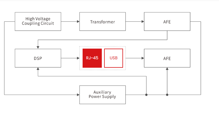
Design Reference
Summary
ESD and surge protection for Power-Line Carrier (PLC) ports is an indispensable aspect of power-line carrier hardware design. PLC systems directly coupled to the mains grid must withstand high-energy surges and human-body electrostatic discharge while simultaneously preserving the integrity of high-frequency carrier signals.
If you are developing smart meters, energy management systems, Industrial IoT devices, or other power line communication products that support PLC functionality, please contact Semiware to discuss your protection requirements and obtain suitable low-capacitance protection solutions.