I. Overview of the RJ11-SLIC Interface
The SLIC (Subscriber Line Interface Circuit) facilitates the connection between various subscriber lines and the switching system.
Subscriber circuits come in various types depending on the switching mechanism and application environment. In stored-program controlled digital exchanges, the primary types are Analog Line Circuits (ALC)—which connect to analog telephones—and Digital Line Circuits (DLC)—which connect to digital telephones, data terminals, or terminal adapters.
The SLIC's analog interface typically utilizes a two-wire telephone line, with the wiring largely located outdoors. Furthermore, due to inherent characteristics, the SLIC is sensitive to external interference; therefore, implementing appropriate protection for the SLIC chip is essential.
II. Surge and ESD Risks Facing RJ11-SLIC Interfaces
2.1 Electrostatic Discharge (ESD) Risks
- RJ11 port handling and mating: Risks arise during equipment commissioning, user connection/disconnection of telephones, and equipment room maintenance; exposure levels include ±6kV for contact discharge and ±8kV for air discharge.
- Friction-induced static: Static charge accumulation caused by wind friction on outdoor twisted-pair cables or the dragging of cables within the equipment room.
- Static discharge due to ground potential differences: Transient discharges resulting from voltage differentials between the SLIC's analog ground, digital ground, and chassis ground.
2.2 ESD Failure Mechanisms and Symptoms
SLICs contain both high-voltage analog channels and 3.3V/1.8V digital control cores (Reset, PCM, SPI); electrostatic transient spikes (nanosecond scale) can cause cross-domain breakdown:
- Breakdown of digital control ports: Breakdown of CMOS gates at RESET, PCM clock, and SPI pins, resulting in symptoms such as audio howling, failure of on-hook/off-hook detection, chip lock-up, and loss of loop feed capability;
- Damage to TIP/RING analog channels: Burnout of internal loop-feed amplifiers and ringing-current driver transistors, manifesting as a lack of ringing, absence of loop current, and chip overheating;
- Latent damage (most insidious): ESD does not cause immediate catastrophic breakdown but leads to a permanent increase in leakage current, resulting in audio distortion and a surge in failure rates after prolonged operation;
- Crosstalk damage to downstream DSP/CPU: ESD surges into the main controller via the PCM bus, causing the entire system to freeze.
2.3 Surge Risks
- Lightning strikes on nearby power lines or cables induce 1.2/50μs voltage surges and 8/20μs current surges on twisted-pair lines via electromagnetic coupling; peak voltages can reach several kilovolts, and peak currents can range from tens to over a hundred amperes;
- Direct lightning strikes on incoming telephone lines generate surge currents reaching hundreds of amperes; without multi-stage protection, this instantly destroys the SLIC, PCB copper traces, and peripheral power supply components;
- Wiring errors or damaged cables allow 220V AC mains voltage to couple into the TIP/RING lines; the resulting sustained high voltage, combined with surges, causes immediate breakdown of the SLIC's high-voltage loop-feed module;
- Switching power supplies and relays in the equipment room generate high-frequency pulse trains that continuously interfere with SLIC analog amplifiers, causing background noise, false ringing, and erroneous off-hook detection.
2.4 Surge Failure Modes
- Avalanche breakdown of internal high-voltage power transistors: Short-circuiting of MOSFETs in the SLIC ringing boost circuit (-112V) or line-feed circuit, resulting in chip overheating and loss of line-feed capability;
- Burnout of differential input operational amplifiers: Damage to TIP/RING front-end buffers, causing a short circuit on one side of the line;
- Melting of PCB copper traces: High surge currents blowing out port traces;
- Internal power supply short circuit: Breakdown from the high-voltage analog domain to the low-voltage digital domain, resulting in the destruction of the main control chip;
- Batch failures: Simultaneous damage to multiple FXS ports during thunderstorms, causing widespread offline status for switch user boards.
III. Test Standards
IEC61000-4-5 (Surge)
IV. Application Block Diagram
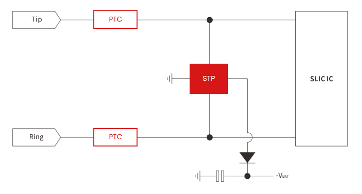 ESD Protection
" class="wp-image-18486" style="width:642px;height:auto"/>
ESD Protection
" class="wp-image-18486" style="width:642px;height:auto"/>V. Recommended Protection Components
In the application block diagram, the recommended STP component is the STP61089B series programmable circuit protector, and the recommended PTC component is the SMD1812-010 series PTC resettable fuse.
5.1 STP61089B Programmable Circuit Protector Datasheet
5.2 SMD1812-010 Resettable Fuse Datasheet
About Semiware
Semiware offers a comprehensive portfolio of overvoltage protection devices. Leveraging its semiconductor technology expertise and experience with end-product applications, the company serves customers across the electronics, automotive, and industrial markets.
Please feel free to contact us with any questions or requirements.