I. Introduction: Small-Signal Transistors in Two-Wheeler BMS
In the design of lithium battery BMS protection boards for two-wheeled electric vehicles, besides core components such as the main control chip, power MOSFETs, and equalization modules, small-signal transistors are also crucial components in the peripheral signal control circuits. Their performance affects the signal control, switching drive, and overall reliability of the BMS.
Among them, the MMST5401 and MMST5551, as a pair of high-voltage complementary transistors, feature small packages, high voltage withstand, and high frequency, and can be used in 48V/60V/72V two-wheeled vehicle lithium battery BMSs and other battery management and control circuits.
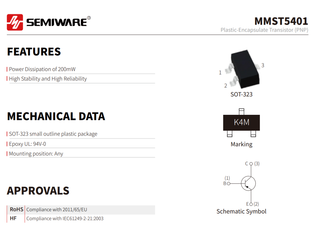
This article will introduce the core electrical parameters and product features of the MMST5401 and MMST5551, as well as typical application scenarios of these two transistors in two-wheeled vehicle BMSs, providing a reference for hardware engineers in selecting peripheral components for BMS.
II. MMST5401 & MMST5551 Core Parameter Comparison Table
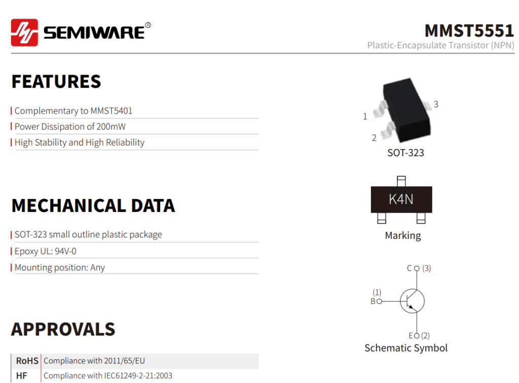
MMST5401 and MMST5551 adopt PNP and NPN structures respectively. Their package forms and some key electrical parameters are highly complementary, and they can be used for signal switching, logic control, and small signal drive circuits in BMS.
III. Core Product Advantages of MMST5401 & MMST5551
Compared to ordinary small-signal transistors, the complementary PNP/NPN structure, high voltage withstand capability, and small package size of the MMST5401 and MMST5551 make them suitable for peripheral signal control and drive circuits in two-wheeled vehicle BMS.
- High Voltage Withstand Capability, Suitable for 48V/60V/72V Battery Systems
- Currently, common lithium battery systems for two-wheeled electric vehicles include 48V, 60V, and 72V specifications. In actual operation, the battery circuit and MOSFET switching may generate certain transient voltages.
- The MMST5401 has a VCEO of -150V, while the MMST5551 has a VCEO of 160V, providing a large voltage margin for BMS signal and control circuits. These devices can be used in small-signal switching and control stage circuits within battery management systems.
- In practical designs, the voltage margin of the devices still needs to be evaluated based on the system's maximum operating voltage and potential transient voltages.
- PNP/NPN Complementarity Facilitates Signal Control Circuit Design
- The MMST5401 uses a PNP structure, while the MMST5551 uses an NPN structure. Depending on the circuit topology, they can respectively handle high-side and low-side signal control, logic level conversion, and switch driving functions.
- Both devices use an SOT-323 package, allowing for a compact layout on BMS protection boards with limited PCB space. This also facilitates standardization of some BOM and surface mount technology (SMT) processes.
- High-Frequency Characteristics, Suitable for Small-Signal Switching and Driving
- Both the MMST5401 and MMST5551 have characteristic frequencies no lower than 100MHz, providing fast dynamic response for small-signal amplification, switching, and driving circuits in a BMS.
- It's important to note that the transistor's fT is not equivalent to the overall protection response time of the BMS system. Actual overvoltage, undervoltage, and overcurrent protection speeds are also related to factors such as the sampling circuit, control IC, MCU, MOSFET driver, and software logic.
- Wide Temperature Range, Adaptable to Complex Operating Environments
- Two-wheeled electric vehicles typically operate under varying ambient temperatures, requiring the BMS protection board to possess good environmental adaptability.
- The MMST5401 and MMST5551 operate within a temperature range of -55℃ to +150℃, meeting the needs of small-signal control and driving applications over a wide temperature range. In practical applications, thermal design should also consider PCB heat dissipation conditions, device power consumption, and the system's operating environment.
IV. Specific Application Scenarios of MMST5401 & MMST5551 in Two-Wheeled Vehicle BMS
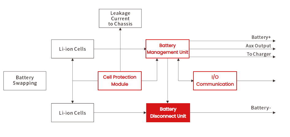
In lithium-ion battery BMS for two-wheeled electric vehicles, power MOSFETs are typically responsible for switching the main charging and discharging circuit, while MMST5401 and MMST5551 are mainly used for peripheral signal control, logic conversion, and drive circuits. Typical applications include the following:
- Signal Switching and Logic Control
- BMS contains numerous circuits requiring high-low level switching or signal control. PNP and NPN transistors can be used to invert signals, perform level conversion, and switch control depending on the specific topology.
- The complementary structure of MMST5401 and MMST5551 helps engineers select the appropriate high-side or low-side control method based on actual circuit requirements.
- Charge/Discharge Enable and MOSFET Control
- BMS typically controls the opening and closing of charging and discharging circuits by controlling power MOSFETs.
- In some BMS circuits, small-signal transistors can be used for MOSFET gate control, enable signal control, or pre-stage drive. For example, when the BMS detects abnormal states such as overcharge, over-discharge, or overcurrent, the control circuit can perform corresponding switching control through the transistor stage.
- The specific circuit design needs to be selected based on the MOSFET's gate voltage, current requirements, and drive topology.
- Alarm and Status Indication Circuits
- Some two-wheeled electric vehicle BMSs are equipped with LED status indicators, buzzers, or other alarm circuits to display battery status or indicate abnormal conditions.
- MMST5401 and MMST5551 can be used as small-signal switching devices to control external loads such as LEDs and buzzers, achieving signal output under different operating conditions.
- Optocoupler Isolation and Interface Signal Driving
- For BMS circuits using optocouplers for signal isolation, small-signal transistors can be used for driving and controlling the optocoupler input or output stages.
- MMST5401 and MMST5551 can perform signal amplification, switching, and logic conversion functions as needed, thereby assisting in signal transmission between the control side and the controlled side.
- For intelligent BMS that uses communication functions such as CAN, RS485, and Bluetooth, whether isolation is required and how transistors are used in the interface circuit should be determined based on the actual communication architecture and circuit design.
Summary
In two-wheeled electric vehicle BMSs, small-signal transistors like the MMST5401 and MMST5551 can be used in peripheral circuits such as signal switches, logic control, MOSFET enable and drive, status indication, and optocoupler interfaces. For 48V, 60V, and 72V battery systems, engineers can select components based on the specific circuit's voltage rating, current, power consumption, drive method, and ambient temperature requirements.
If you are developing a two-wheeled electric vehicle BMS, lithium battery protection board, or other battery management equipment, please contact us to learn about the detailed parameters and application solutions of MMST5401, MMST5551, and other small-signal transistor products.