As a hardware engineer, have you ever encountered the following situations?
When a project enters the component selection phase, finding a Zener diode that meets specific requirements often involves simultaneously comparing data sheets from multiple manufacturers—repeatedly weighing parameters such as reverse leakage current (IR), Zener voltage (VZ), power dissipation (Pd), and package dimensions. Alternatively, the originally selected model might suddenly face stock shortages, forcing you to seek an alternative solution—yet leaving you unsure whether different product series can serve as direct replacements.
This article provides a systematic overview covering key parameters, classifications of mainstream series, package correspondence, and alternative selection methods for Zener diodes. Its aim is to help engineers quickly master the core essentials of Zener diode selection.
I. The Core Value of Zener Diodes
The Zener diode—also known simply as a "Zener"—derives its name from the American physicist Leonard Zener.
It is a specialized type of diode designed to operate specifically within the reverse breakdown region. Once the reverse voltage applied across the device reaches its breakdown voltage, the voltage across its terminals remains relatively stable. Consequently, Zener diodes are widely utilized in circuits for voltage regulation, voltage referencing, overvoltage protection, and voltage limiting.
Simply put, the core function of a Zener diode is to:
Provide a stable and reliable reference voltage to a circuit, even in the presence of input voltage fluctuations or changes in load conditions.
II. Operating Principle: From "Reverse Breakdown" to "Voltage Stabilization"
1️⃣ Zener Diode Circuits vs General Diode Circuit
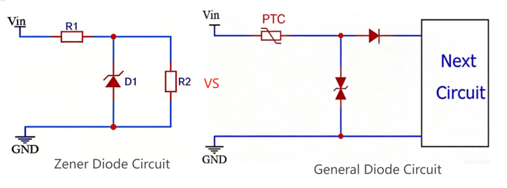
| Feature | Zener Diode | Standard Diode |
| Operating Region | Operates in the reverse breakdown region. | Operates in the forward conduction region. |
| Behavior Under Reverse Voltage | When the reverse voltage reaches or exceeds VZ, the diode enters regulation mode and maintains a nearly constant voltage. | Excessive reverse voltage may cause breakdown and permanent damage. |
| Voltage-Current (V-I) Characteristic | In the reverse breakdown region, current can vary significantly while voltage remains nearly constant. | In the reverse region, almost no current flows except for a very small leakage current. |
2️⃣ Why Can Zener Diodes Regulate Voltage? — A Detailed Explanation of the Reverse Breakdown Mechanism
While ordinary diodes are typically designed to avoid entering a breakdown state, Zener diodes are designed to do precisely the opposite: they are engineered to operate stably and continuously within the reverse breakdown region.
When the reverse voltage applied across the device reaches its specified Zener voltage (Vz), the current flowing through the diode increases rapidly; however, the voltage across its terminals remains essentially constant, thereby achieving the effect of voltage regulation.
Depending on the specific Zener voltage value, Zener diodes primarily exhibit two distinct breakdown mechanisms:
🔹 Zener Breakdown (Typically occurs below 5V)
When the doping concentration within the PN junction is sufficiently high, a very strong electric field is generated. Once the reverse voltage reaches a certain threshold, electrons are able to tunnel directly across the PN junction, thereby generating a current; this phenomenon is known as Zener breakdown. This phenomenon primarily occurs in low-voltage Zener diodes rated at 5V or below.
🔹 Avalanche Breakdown (Typically above 6V)
As the reverse voltage continues to increase, electrons accelerate to high speeds under the influence of the electric field. These electrons repeatedly collide with other atoms, generating additional electrons and triggering a "chain reaction" that causes the current to rise rapidly; this phenomenon is known as avalanche breakdown. It primarily occurs in Zener diodes rated at 6V or above.
III. How Zener Diode Parameters Affect Actual Voltage Regulation Performance
1️⃣ Parameters Determining "Stability"
1. VZ (Zener Voltage):
Defines the target value of the output voltage; however, this is not a fixed point but rather an allowable range.
2. IZT (Test Current):
The reference current point defined by the manufacturer for parameter specification, used to ensure consistency in the testing of VZ and dynamic resistance.
3. IZK (Minimum Operating Current):
Below this current level, the voltage regulation capability degrades significantly.
2️⃣ Parameters Determining "Risk of Burnout"
1. PZM (Maximum Power Dissipation):
The maximum thermal limit that the device can withstand.
2. IZM (Maximum Current):
The limiting current derived by working backward from the maximum power dissipation.
👉 Under no circumstances should IZM be exceeded; doing so poses a significant risk of device failure.
3️⃣ Parameters Determining "Power Efficiency"
IR (Reverse Leakage Current):
Crucial for low-power systems, particularly in battery-powered devices.
👉 The higher the temperature, the more severe the leakage becomes.
4️⃣ Parameters Determining "Regulation Quality" (Dynamic Performance)
1. ZZT (Dynamic Resistance):
The lower, the better; it indicates a "stiffer" voltage source.
2. bZZK (Dynamic Resistance at Knee Point)
An indicator of stability under light-load conditions.
👉 When operating close to the IZK point, the voltage regulation performance degrades noticeably.
IV. Zener Diode Selection: Understanding the Datasheet in 5 Minutes
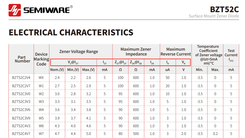
1. Check VZ: Verify that the Zener voltage meets the circuit's requirements, and simultaneously check if its tolerance (e.g., ±5%, ±2%, ±1%) satisfies the design specifications.
For example, when a 5V voltage reference is required, selecting a 5.1V Zener diode is often more appropriate than selecting a 4.7V one.
2. Check PZM: Calculate the actual power dissipation based on the operating voltage and maximum current:
P = VZ × IZ
Ensure that the actual power dissipation remains below the device's rated power dissipation, and leave a certain safety margin. It is generally recommended to keep the actual dissipation within 50% to 70% of the rated capacity to enhance reliability and extend the device's lifespan.
3. Check the Operating Current Range: Is effective voltage regulation possible? Key Parameters to Focus On:
- IZT (Test Current)
- IZK (Minimum Zener Current)
- IZM (Maximum Zener Current)
During the design phase, ensure that the current flowing through the Zener diode remains within the range of IZK to IZM across all operating conditions.
4. Check ZZT: ZZT (Dynamic Resistance) indicates the Zener diode's ability to suppress voltage fluctuations.
The lower the value, the more stable the output voltage remains when changes occur in the load or input current.
5. Check the Temperature Coefficient: If the product is required to operate in environments subject to significant temperature variations—such as outdoor settings, industrial control systems, or automotive electronics—particular attention should be paid to the temperature coefficient of the Zener voltage.
The lower the temperature coefficient, the less the output voltage will drift in response to changes in ambient temperature.
6. Check IR: For battery-powered devices, portable products, and low-power systems, select components with a low IR (Reverse Leakage Current) value whenever possible.
In Summary:
Voltage (VZ) → Power Dissipation (PZM) → Current Range (IZK–IZM) → Dynamic Performance (ZZT), followed by detailed specifications such as temperature characteristics and leakage current.
Conclusion
Understanding key Zener diode parameters such as VZ, PZM, IZT, IZK, IR, and ZZT can help engineers select the right device more efficiently and achieve better voltage regulation performance in practical designs.
Semiware Zener Diode Solutions
Semiware offers a wide range of Zener diode series, including BZX84, BZT52, MM3Z, and MMSZ, covering multiple voltage ratings, power levels, and package options.
https://en.semiware.com/products/zener
If you are designing power supplies, industrial equipment, consumer electronics, or communication systems, contact Semiware for reliable Zener diode solutions and component selection support.


Comments (0)